Veroboard 12v Adjustable Power Supply |
DisclaimerThis
circuit assumes that you have some knowledge of Electronics, if you have
none, then I do not recommend you proceed. I take no responsibility for
any injury or damage that this circuit may cause. The circuit that is
shown did work for me and I had no problems with its operation. Use of the
information presented here is subject to the terms of usage, which are
shown at the bottom of this document. Circuit DescriptionThis is
an adjustable MOSFET Power Supply that uses as 12 volt Car / Motor Cycle
Battery as a power source. It can be used for many things, Speed
Controller, Light Dimmer, Foam Cutting Bow Power Supply, Glow Plug Driver.
etc. I have used it for a Foam Cutting Bow Power Supply and a Glow Plug
Driver, using a 12v Battery as a power supply. The
general circuit uses a 555 Timer that is configured to turn the MOSFET on
and off at a high speed. This in effect gives an increase/decrease in
Voltage/Current across the load section of the circuit. When the
Potentiometer is turned one way, the frequency of the MOSFET being turned
on lessens, when turned the other way it increases the rate. You can
use most general MOSFET’s in the circuit; I have used a BUZ71, BUK456
and BUK 457. I have matched the load of what I was using it for with the
MOSFET. Most of the time I have not had to use a Heat Sink on the
MOSFET’s, as the loads were low. However some uses may require a Heat
Sink, please follow the MOSFET’s Manufacturers recommendations for the
load you are using the circuit with. The
circuit’s supply voltage is only limited by the components used. If you
wish to use it for more than 12volt supply voltages, please ensure that
you have components to suit the need. This may also require the addition
of a power regulator to supply current to the 555 timer. If this
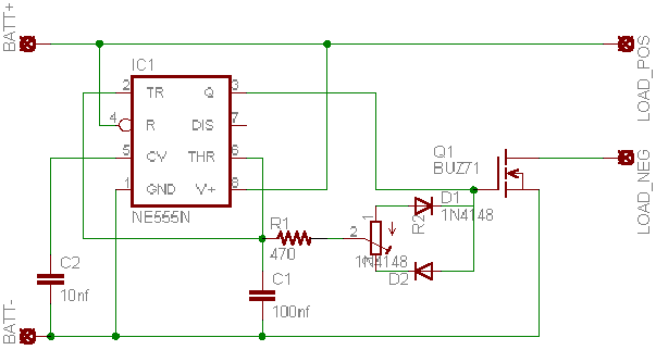
does not scare you, then push on.. The schematic is shown below;
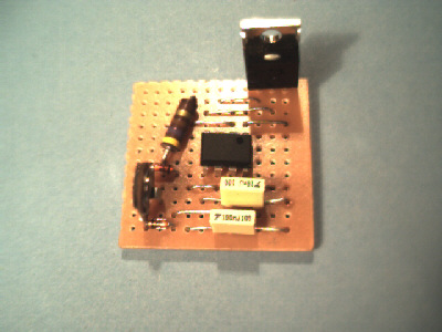
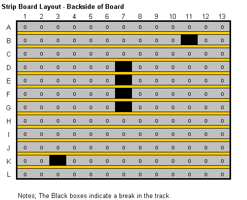
It has been built on a Veroboard of approx. 30mm x 30mm. The following is the layout for the board, showing the break points on the back of the board.
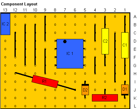
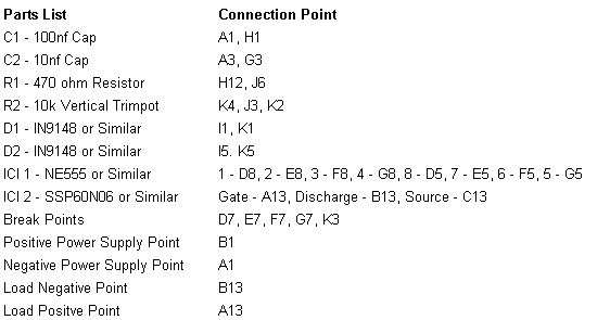
The component layout is shown below;
Please make sure you fit the IC’s in the right way, check the Parts list for the connection points for all components. The Parts required are;
Terms of Usage This information can be used only for non-commercial purposes, it can only be used for commercial purposes with the written approval of the Author. It can be freely distributed as long as reference is made to the author wherever it is displayed or used. The Author takes not responsibility for any inaccuracies in this document and also for any loss, damage or injury the information presented here may cause. If you have a all correction, contribution or suggestion that you wish to share with the Author, please send an email to craig@willingtons.com replies will not be guaranteed. |